The same work was done with HCL COMNET and ERNET
Antenna refurbishment/ Maintenance
Installation:
Antenna Wash:
Antenna was washed with water using the pressure pump.
Antenna Maintenance:
Mechanical maintenance of the antenna done removing the rust/blockage using WD 40 and greasing on Jacuators as well as bearing by inserting the grease using grease gun.
Oil filled in the Azimuth and Elevation gear box
Antenna Painting:
Painting of antenna structure was done with QD type using the spray machine. In total used ~120 liters
Antenna Motors:
Removed the existing motors and installed the new motors. Also repaired the old motors and kept as spare.
Antenna Accessories:
New bellow covers for the Azimuth and Elevation motors.
Mechanical brackets for Azimuth and Elevation encoder
Mechanical frame for the Antenna drive unit.
Ladder to maintenance
Antenna Earth Pits:
Three chemical earthing (maintenance free) pits were done. Two earthing pits cascaded for lighting grounding and one earth pit for the antenna grounding
Earth pit resistance is measured < 1 Ohms
Antenna Lighting/ Grounding:
New lighting copper road placed on the top edge of the reflector and had the copper cable with proper routing to base of antenna and from there to earth pit by chipping the platform to earth pith. The floor area chipped was properly filled with cement mixture
Antenna Aviation Lamp:
Had aviation lamp of LED type with photo synthetic the top of the reflector and power extended using the shield cable from the Antenna Drive unit.
Antenna Feed Membrane
Feed membrane was provided if required in near future
Antenna to Indoor cable tray
Existing cable is repaired, cleaned and proper painting done. The cable try was closed with new covers
Antenna Feed motorization:
Antenna feed was manual, so motorization done having the mechanical bracket, and motor with reduction gear.
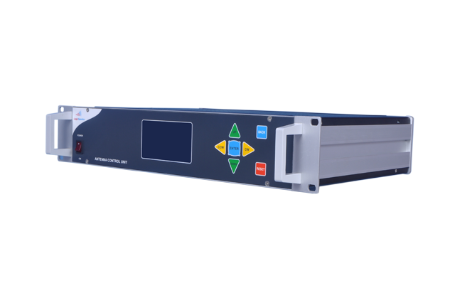
Antenna Control System:
Dismantled the old control system (non-functional) and installed new antenna control system i.e out door Antenna Drive unit (ADU) near the antenna having the frame and indoor unit Antenna control unit (ACU).
ADU and ACU were connected using the multicore teflon cable (via overhead cable try) and also encoder (Azimuth, Elevation and FEED) were connected to ACU having multi core Teflon cable
Cables from ADU:
Power cable to motors (i.e Azimuth motor, Elevation motor and feed motors)
Limit Switches
Power for ACU was provided from PDU and three phase power to ADU from the existing power socket with new cable
Proper cable routing was done.
Beacon Tracking Receiver:
Beacon receiver was installed in the RF rack and Power from the PDU
Beacon receiver L band input was provided from the RF to L band converter
Beacon receiver output voltage was connected to ACU having BNC interface cable.
Waveguide
New elliptical wave guide connected from amplifier output to antenna feed input with proper routing via overhead cable try
Pressure Window
Two pressure windows were kept one at wave guide joint near the amplifier and other at the feed end. To block the pressure going into amplifier as well as feed and to maintain in the wave guide.
Dehydrator
Automatic dehydrator was installed in the RF rack and power from the PDU. The pressure outlet was connected to waveguide pressure input port using the tube.
Commissioning:
Antenna control system commissioning done and tested the functionalities of the antenna movement in three axis
Integrated with beacon receiver and tested the tracking functionalities
Dehydrator pressure set and made operational.